

I remember meeting Ken McElvain at Silicon Compilers for the first time back in the 1980’s, he was a gifted EDA tool developer that did a lot of coding including logic synthesis, a cycle-based simulator and ATPG. Mentor Graphics acquired Silicon Compilers with Ken included, and he continued to create another logic synthesis tool at Mentor, however the allure of starting up his own company set in and Ken then founded Synplicity, eventually acquired by Synopsysin 2008. After all of these years the Synplify tool is still setting the high-water mark for logic synthesis in FPGA devices. Joe Mallett at Synopsys wrote a four page white paper recently, so I read it to better understand the four steps for logic synthesis in FPGA designs:
[LIST=1]
Initial Design Setup and Configuration
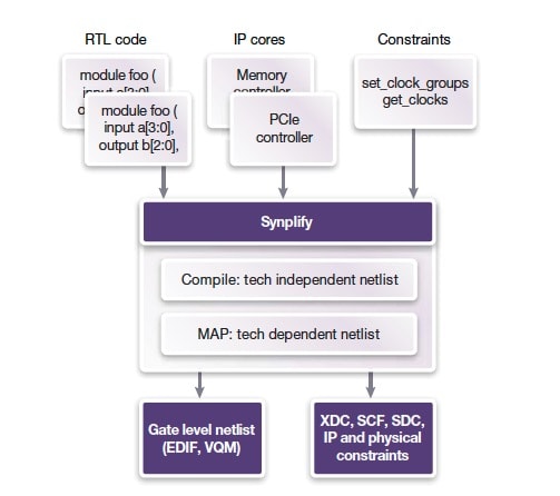
Gone are the days of starting with a blank sheet as a design starting point, instead to get to market more quickly the best practice is to re-use IP blocks from previous designs, re-use IP from other groups within the company, purchase new IP from trusted vendors, or use IP provided by the FPGA vendor. These IP blocks will typically have RTL source code along with constraint files for the logic synthesis tool. Here’s the design flow showing how the RTL code, IP cores and constraints go into the Synplify logic synthesis tool, creating your gate level netlist and technology-specific output files:
First Working Hardware
One acronym that you quickly learn with logic synthesis is Quality of Results (QoR), which means reaching the desired clock speeds, input setup and hold times, output delay times, and fewest number of gates, all at an acceptable power level. A smart logic synthesis tool like Synplify can quickly infer what clocks are in your design, however you can always define internal clocks as needed to further constrain the design and achieve objectives.
Related blog – One FPGA synthesis flow for different IP types
When constraints for logic synthesis are all in place, then the Synplify tool does its work to generate the compiled design, ready for physical implementation by the FPGA vendor place and route tool. To speed up logic synthesis run times the approach used by Synplify is called distributed synthesis. Using runtime acceleration in Synplify gives you results quicker, and you can even do incremental synthesis on parts of your design are changing. Most modern EDA tools have adopted this approach of distributed computing to get results more quickly. You get to decide which is best for your project, running Synplify on just one machine, or across a server farm.
High Visibility FPGA Debug
Debug and verification of your new design will likely take more time and effort than the original design entry does. So how do you get visibility and traceability of your complex design with all of those IP blocks included? The good news is that you can select any set of internal signals for sampling or triggering during simulation using Identify integration, something built-in to Synplify. With this list of selected signals you now have an instrumented design, and using the debugger you can analyze results at system speeds which makes for faster design debugging.
As you debug your design and make changes, then there’s a re-compile required and with Synplify you can do a parallel incremental synthesis, as shown below:
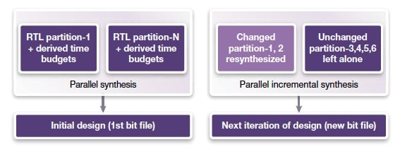
This accelerated approach lets you get in multiple iterations per day, to help meet your time to market deadlines.
Tuning the System for Performance
When the design meets all of the functional requirements and debug is behind us, then the fourth step is focused on reaching the total system-level performance. The FPGA synthesis tool can be further constrained to reach timing metrics, but if you over-constrain the design then it will just increase the run times for synthesis and the vendor place and route tools. Here are some best practices to consider when using Synplify to tune for timing QoR:
- For failing timing paths look at the logic along the path and see if you can use fewer levels of logic
- Follow recommended RTL coding guidelines for both synthesis plus place and route (think Apnotes)
- Using timing models for black boxes (i.e. IP blocks)
- During place and route increase the placement effort if there’s room for improvement in the placement
- Fix any synthesis project errors prior to starting place and route
- Review the timing analysis report to direct your constraints
- Reduce high fanout nets in Synplify, add more pipelining and try sequential optimizations and re-timing
- Find and remove any un-needed resets
- Choose your critical paths to be on the same die of multi-die FPGA devices
Related blog – Why FPGA synthesis with Synplify is now faster
Summary
FPGAs have grown dramatically in popularity from the earliest days when used only for glue logic between expensive ASICs, to now encompassing processors, complex IP blocks, high-speed serial channels, optimized memories, and millions of gates. By using a logic synthesis tool like Synplify in the design flow you will find that these four steps can get done at a rapid pace.
Read the complete four page white paper here
Share this post via:


Comments
There are no comments yet.
You must register or log in to view/post comments.