

Verilog History
Prabhu Goel founded Gateway Design Automation and Phil Moorby wrote the Verilog language back in 1984. In 1989 Cadence acquired Gateway and Verilog grew into a de-facto HDL standard. I first met Prabu at Wang Labs in 1982 where I designed a rather untestable custom chip named the WL-2001 (yes, it was named to honor 2001 A Space Odyssey) and was lectured about the virtues of testability, oh well.
Learning Verilog
Today you can learn Verilog by a variety of means:
[LIST=1]
I’ve learned Verilog through self study and kept in touch with a corporate trainer named Tom Wille who operates TM Associates, we both worked at Mentor Graphics. Several years ago Tom asked me to update and deliver a Verilog class for Lattice Semiconductor to use:
- Lattice ispLever, an FPGA design environment
- ModelSim for Verilog simulation
- Synplify for logic synthesis
I’ve delivered the Verilog class to both Lattice Semi and other companies in the US. Recently I updated the Verilog class again and trained a group of AEs at Lattice Semi in Hillsboro, Oregon using:
- Lattice Diamond, the newest FPGA design environment
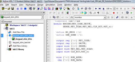
- Aldec for Verilog Simulation
- Synplify for logic synthesis
Class Experience
Each AE brought in their own laptop computer loaded with software and I handed out a thick binder with lecture material and notes, and a smaller binder for lab exercises. Most of the AEs used Aldec and Lattice Diamond using Microsoft Windows however one AE ran ModelSim using Linux. Some of the reasons for having an on-site Verilog training class are:
[LIST=1]

In three days we covered 12 units of study, typically two units before lunch and two units after lunch. Here’s the general outline we followed:
Day 1
Unit 1: IntroductionCoding and synthesizing a typical Verilog module to be used in the wireless chip.
- Synthesis-friendly features of Verilog-2001
- Migrating the module from an FPGA prototyping technology to a submicron ASIC technology
- Wireless chip design spec
Unit 2: Combinational Logic
- Effective use of conditional constructs (if–else, case,casez, ?:)
- Decoding. Priority encoding
- Code conversion. ROM usage
- Multiplexing/demultiplexing
- Iterative constructs (for, while, disable)
- Signed/unsigned arithmetic
- Using concurrency
Unit 3: Sequential Logic
- Sequential building blocks
- Registers with synch/asynch reset and clock enable
- Parallel/serial converter
- Ring counter
- Edge detector
- Using blocking vs. non-blocking assignments
- Non-synthesizable constructs and workarounds
- ASM (algorithmic state machine) charts as an aid to sequential-machine design
Unit 4: Block Integration
- Chip-level design and integration issues
- Coding above the block level
- Multiple clock domains
- Partitioning an entire chip into modules
- Separating blocks with different design goals
- Registering outputs
- Maximizing optimization
- Instantiating IP blocks such as Synopsys DesignWare
- Instantiating I/O cells using generate loops
Day 2
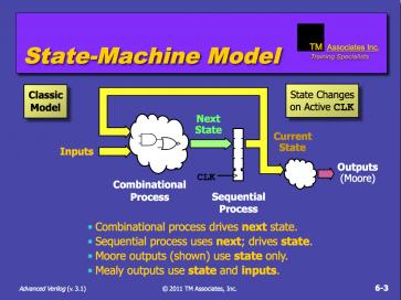
Unit 5: FSMs and Controllers
- Coding FSM-oriented designs
- ASM (algorithmic state machine) chart usage
- Mealy vs. Moore insights
- Modified Mealy FSM with registered next-outputs
- Hierarchical FSMs
- Controller for wireless chip
- Datapath/controller paradigm
Unit 6: Getting the most out of your tools
- Synthesizable HDL subset
- Unsupported constructs
- Excluding simulator-oriented code
- Using parameters and localparam
- Name-based redefinition
- Text substitution
- Managing code modules
- Using include directives and definition.vh files
- Coding for reuse and portability
Unit 7: Coding for Area
- Classic area/delay trade-off
- Avoiding excess logic
- Reducing ASIC gate count or FPGA LUT usage
- Minimizing algebraic tree nodes
- Sharing arithmetic resources
- Sharing non-arithmetic logic like array indexing
- Cacheing recomputed quantities
- Scheduling over multiple clock cycles
Unit 8: Coding for Performance
- Parallelizing operations
- Minimizing algebraic tree height
- Resource implementation selection
- Exploiting concurrency
- Accommodating late input arrivals
Day 3 Unit 9: Verification
- Verification definition, methodology
- Testbench architecture
- Clock generation
- Timescale
- Stimulus generation
- Sampling response at regular intervals or on change
- Comparison of responses
- Using $random
- Using fork–join
Unit 10: Testbench Techniques
- Encapsulating tests within tasks
- Self-checking testbenches
- File-oriented testbenches
- Using $readmem
- Fixed vectors
- Bus functional models
- Synchronizing stimuli
- Named events
- Accessing the Verilog PLI
Unit 11: Avoiding Simulation Pitfalls
- Weaknesses of Verilog-2001
- Truncation and other risky coding constructs
- Timescale pitfalls
- Avoiding race conditions during simulation
- Avoiding simulation-synthesis mismatches
- Avoiding simulator bottlenecks and improving performance
Unit 12: Advanced Topics
- Bottom-up vs. top-down verification methodology
- Emergence of static verification
- Coding guidelines for formal equivalence
- Co-simulation using Vera
- Scan-based testing
- DFT guidelines
- Future directions.
The pace is fast and the group of AEs had many questions that were answered and clarified using the white board. More than half of the time is spent in the labs where students really get to apply the theory in a practical way by coding Verilog, debugging and then verifying correct results. We code both designs and test benches.
In this particular class we did uncover one subtle difference between Verilog simulation results using Modelsim versus Aldec. The student using Modelsim was able to tweak the one lab design to pass the test bench.
Summary
If you have a group of engineers that needs to learn Verilog for the first time, or just increase their Verilog understanding then consider contacting Tom Wille to find out if an on-site class might be of value. His company also offers VHDL training and has been in business for many years using a variety of freelance instructors.


The Data Crisis is Unfolding – Are We Ready?