
The phrase “where the rubber meets the road” is especially apt when it comes to discussions about the Internet of Things. The obvious interpretation is that dissimilar things are being put together in a mutually dependent fashion. When I hear the phrase I always think of the things that can go wrong, such a tire sliding instead of sticking to the road. In the world of IoT development there are plenty of parallels. Most often we are talking about dissimilar worlds – physical and digital, and the challenges of combining them. Just as in tire (or road) design, there are plenty of limitations that make the task of building effective IoT devices more difficult.
The classic model is for an IoT edge device to have one or more sensors, on-board processing power and the means to connect to the internet – usually wirelessly. All the familiar limitations apply, such as low power requirements, performance/cost tradeoffs, packaging, etc. The first step is to develop a proof concept, which, while useful, may omit the evaluation of many key performance characteristics. So, what happens next? This is the question that Mentor seeks to answer in their recent white paper entitled “Proof-of-Concept: The Day After”, by Jeff Miller, Product Marketing and Strategy.
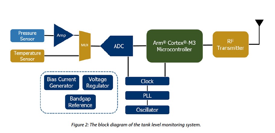
In the white paper, Jeff takes us through the steps of development for a tank fluid level monitoring system. This would have wide applicability in breweries, wineries or other beverage facilities, for a start. For instance, it could be used to detect if fluid levels were dropping due to a leak. Mentor’s example system consists of a pressure sensor which could then be used to infer the height of fluid above the sensor. It has an analog to digital converter that is connected to a processor. There is also an RF transmitter to provide internet connectivity. In the proof of concept, that they prepared prior to the prototype stage, they used a voltage reference instead of the actual pressure sensor. In the prototype, there are a number of supporting circuits, including an oscillator, PLL and clock which is used by both the processor and the ADC.
For the prototype, they used a MUX to add the option of including a temperature sensor in future versions. In the whitepaper, they go through each step to design a fully working system. To ensure high sensitivity they employed a Wheatstone bridge to help measure the change in resistance in the sensor. They instantiated all the elements of the design and then performed simulations. They opted to use an ARM Cortex M3 instead of an M0. This was done mostly to provide more flexibility in the final system, but was easily possible because the development IP for both processors is available under the ARM DesignStart program. They used the CodeBench development system which also supports both processors.
With the software written, a system simulation is possible. The whitepaper shows the steps involved in this. Lastly the communication block is brought in. With bidirectional communication, cloud services or a web front-end can be implemented. Also over the air updates would be possible with bidirectional communication.
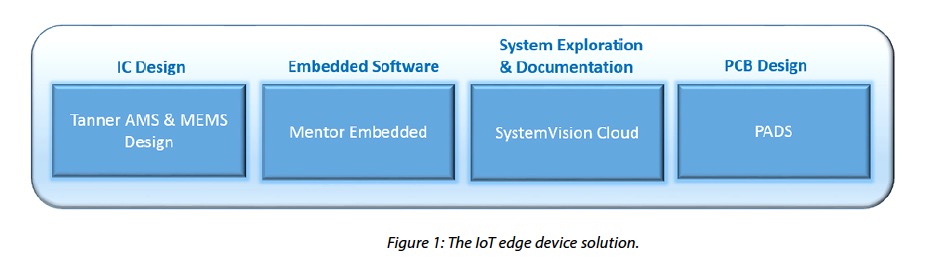
To complete a prototype project like this, a suite of tools is needed that covers custom IC design, PCB, embedded software, and system simulation. Mentor offers a complete design flow like this that is tailored for the needs of IoT Edge Device developers. That coupled with the easy access to ARM processors, suitable for these kinds of applications, dramatically simplifies the design and development process. At the end of the day all of the system’s the performance characteristics need to be fully optimized to develop a competitive product that provides differentiation in the marketplace. The detailed whitepaper is available for download on the Mentor website.
Share this post via:


Comments
There are no comments yet.
You must register or log in to view/post comments.