
Consumer electronics demand aggressive mechanical enclosure design — product volume, weight, shape, and connector access are all critical design optimization criteria. Mechanical CAD (MCAD) software platforms are used by product engineers to develop the enclosure definition — the integration of the PCB design (or, potentially, a rigid-flex assembly) into the MCAD model enables the engineer to verify the mating of the enclosure and electronics, and submit the model to thermal, structural, and EMC/EMI analysis.
Traditionally, the (final) PCB definition was exported from the ECAD design platform using the .idf representation, short for “intermediate data format“. An (initial) .idf description would be exported from the MCAD toolset to reflect the starting PCB topology, with connector placements, mounting holes, keep-out areas, etc.
Yet, the .idf format was not conceived to support the requirements of current product designs, where iterative collaboration between MCAD and ECAD environments is required. To address the needs of MCAD and PCB designers, an industry consortium pursued the definition of a new standard, commonly known as .idx (named after the file extension used, short for “incremental design exchange“). Specifically, the .idx format supports the following key features:
- all design objects are assigned an identifier
Electrical components, holes, keep-outs, mechanical components, etc. are all given a unique designator, which enables the main .idx characteristic, listed next.
- incremental data exchange
IDX enables MCAD/ECAD systems to optimize the amount of data exchanged during design iterations, and track the change history.
- data is represented using XML schemas
An .idx file is an XML document, which is readily extendible as future requirements arise.
- rich geometry descriptions are supported
IDX uses the definition of “curvesets“, which are assigned a vertical extent to expand the 2D description into 3D. Objects are described using these curvesets; inverted shapes represent a void in an object.
- roles
A “role” can be associated with any item (i.e., a collection of objects), which assigns rights and responsibilities for item updates to specific team members. For example, one ME may own the board shape, while another owns connector and mating hole locations; a PCB engineer may own component locations. The .idx format also supports request/accept/acknowledge handshaking for proposed updates, before changes are applied from one design domain to another.
- properties
Components can be assigned property values, characteristics of specific interest to both MCAD and ECAD analysis (e.g., power dissipation, component mass, physical clearances around the component).
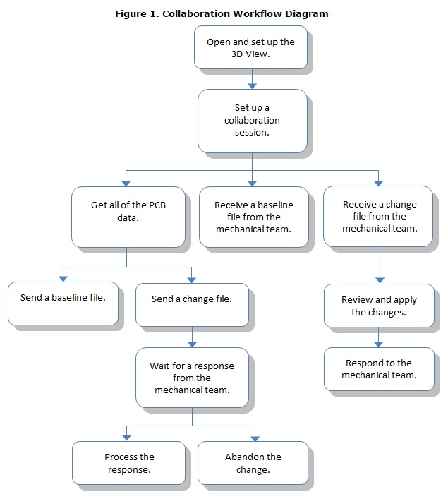
The IDX representation is used by MCAD and ECAD toolsets to exchange incremental updates, after a “baseline” .idx exchange of the initial product definition. A general workflow is depicted in the figure below.

The identifiers in the baseline description then enable exchange of updates to the design — e.g., addition/deletion/re-positioning of components, changes to board shape, relocating a connector or mounting hole, etc.
At the recent PCB Forum in Santa Clara held by Mentor (a Siemens business), the Xpedition team described how .idx has enabled a highly productive MCAD/ECAD collaboration design methodology. (Mentor and PTC were the original drivers of this new standard for mechanical/electrical data modeling and information exchange.) A key feature added to the Xpedition platform has provided the PCB designer with a 3D model visualization of the MCAD data.
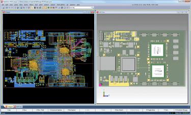
The figures below illustrate the concurrent 2D/3D views in Xpedition, which can include visualization of the Cu data, as well. The incremental characteristics of the .idx file are leveraged in Xpedition — proposed changes imported from the MCAD platform are highlighted, for the PCB engineer to quickly pinpoint areas to review. (Note that Cu data would be exported from Xpedition in the .idx description and merged into the MCAD model, for both physical checks and EMC/EMI analysis.)
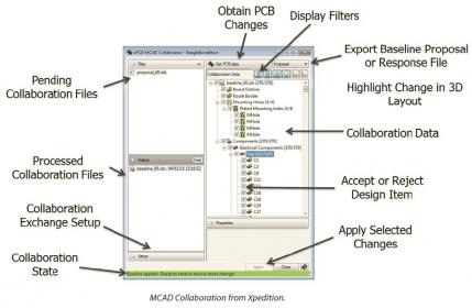
A common property applied to an .idx object is the “lock/unlock” status — a role member can assign a lock property to prevent updates. The Xpedition Data Manager tracks the .idx history, from the baseline through subsequent MCAD/ECAD proposal/response exchange transactions. The figure below illustrates the data management and change notification features of the MCAD Collaborator utility in Xpedition.
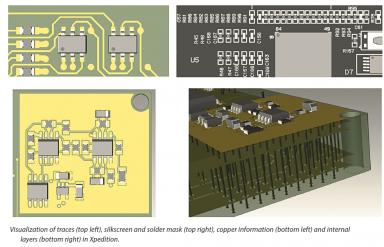
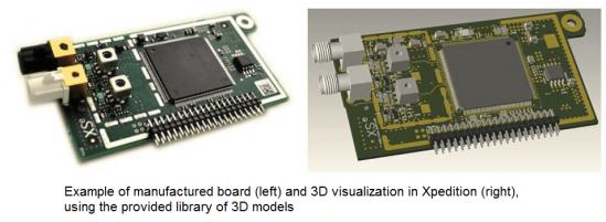
Mentor provides a rich library of existing 3D component models for PCB visualization — the figure below illustrates how the PCB designer’s view in Xpedition compares to the final manufactured board.
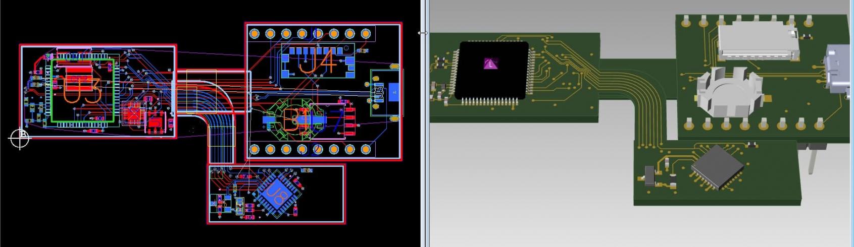
The Mentor Xpedition team also provided a demo of the rigid-flex support within the collaborative design environment. The figure below illustrates the concurrent 2D/3D views of a rigid-flex assembly — 3 PCB’s with multiple (physically overlapping) flex cables.
The complexity of current products requires a close interaction between mechanical and electrical teams. The transition from the .idf to .idx data exchange formats between MCAD and ECAD tools offers a significant benefit to the design methodologies in each domain. Specifically, a PCB designer can make a broad set of design optimizations, and quick export the updates to the MCAD engineer for review. The ECAD platform needs to support .idx exchange — a key feature includes 2D/3D visualization for the PCB designer. Mentor’s Xpedition toolset is focused on enabling this collaborative MCAD/ECAD flow.
For more information on upcoming Mentor PCB Forum dates, please follow this link.
For information on the 3D visualization support in Xpedition, please follow this link.
For general information on ECAD/MCAD Collaboration in the Xpedition platform, please follow this link.
-chipguy
Share this post via:


Comments
There are no comments yet.
You must register or log in to view/post comments.