
ICs for consumer electronics are often battery powered, which are considered low voltage designs. On the other end of the IC spectrum are high voltage devices used in many industrial applications like: automotive, aerospace, data centers, transportation and power generation. Transistors made from SiC (Silicon Carbide) are often used for these high voltage designs because of the higher breakdown voltages made possible by this semiconductor material. Creating the actual SPICE parameters for SiC devices requires either measurement data from a fabrication run or the use of TCAD tools. I attended a webinar hosted by Silvaco this week to become aware of their TCAD to SPICE flow for SiC devices.
Related: Silvaco News: Silicon Valley, China and Korea
Meshing and field solvers are used in TCAD software tools to model and simulate the Si and SiC technology structures. Here’s what a typical mesh looks like:
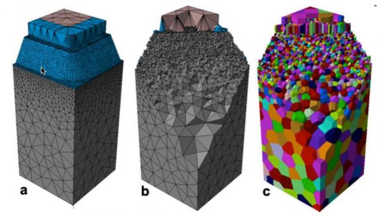
Meshing: a) Exterior. b) Interior, c) Finite volumes
The Silvaco technology uses Delaunay meshes to help minimize device simulation times while maximizing the stability and accuracy of the results. Field solving is accomplished with their PAM solver, a domain decomposition type solver that runs in parallel using MPI (Message Passing Interface). To simulate the breakdown voltage on a device with 200K tetrahedrons required under 1 hour using 4 CPUs.
Silvaco’s device simulator takes into account many physical mechanisms to provide accurate results:
- Monte-Carlo implantation
- Impurity concentration-dependent mobility
- Temperature dependent saturated velocity
- Anisotropic mobility
- Anisotropic impact ionization
- Carrier-carrier scattering
- Schottky parabolic field emission model
- Bulk and interface state model
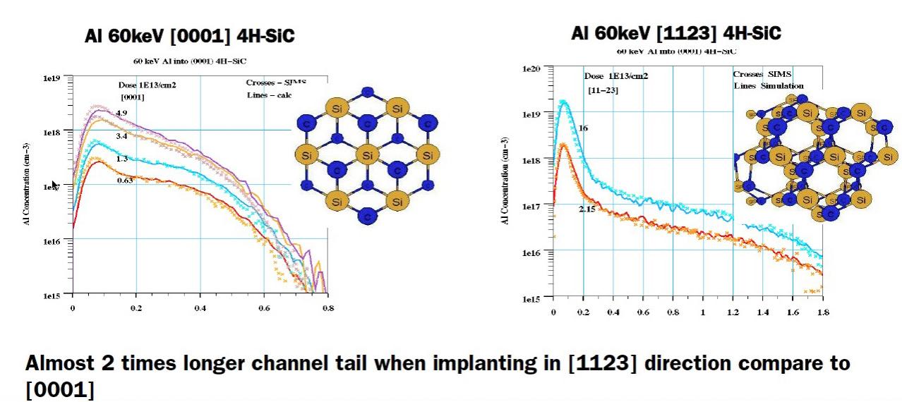
Implant profiles for SiC depend on both the wafer orientation and ion beam direction. Here’s a comparison of implant profiles for two different orientations:
TCAD users choose between 3D modeling for accuracy in many SiC simulations, although 2D can also be simulated to reduce the run times. Other modeling decisions include when to use square versus rounded corners on materials. Here’s an example comparing a 3D trench IGBT of SiC breakdown simulation:
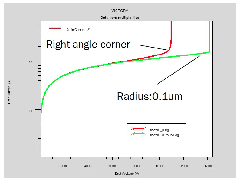
Drain Current vs Voltage
The red line shows lower drain voltage results with square corners, while the green line shows the higher drain voltage results with rounded corners and is more accurate.
Related: Modeling and Analysis of Single Event Effects (SEE)
More TCAD results were presented showing how square versus round corners affected Vt values, and how breakdown voltage changes with the number of guard ring structures selected. The complete flow from TCAD to SPICE with Silvaco tools enables a process engineer to create a Design of Experiments for process exploration:
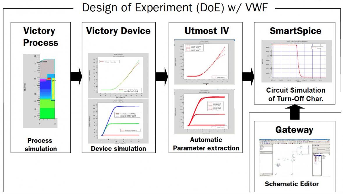
Virtual Wafer Framework (VWF)
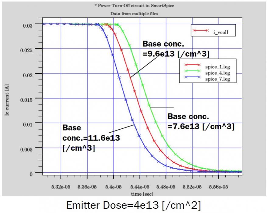
Using this VWF you can actually correlate process variation to circuit performance. Here’s an example where you can compare the power turn-off current in a circuit as a function of emitter dose concentration:
Summary
Silvaco has a complete TCAD to SPICE flow that works well for accurately modeling many technologies like: SiC, Silicon, Trench MOS and DMOS. Engineers at foundries and IDMs can use these TCAD tools to create PDKs, ready for use by circuit designers of power devices. View an archive of this full webinar here.
Related: AN AMS and RF IC Design Flow
Q&A
Q:Are there any other solvers for 2D PAM?
Our solvers can be used in both 2D and 3D. The PAM solver is recommended for iterative, because it supports multi-threading.
Q: Is it possible to link DOE and SmartSPICE without using VFW?
Yes. Although VWF integrates all needed tools together, making it simpler to use.
Q: What kind of precision do your tools support?
We use 64 bit precision, and can also do 80, 128, 256 bit. Simulation time increases with precision.
Q: Could you share info about calibrating TCAD versus measurement for mobility traps?
Calibrating requires some measurement first. Mobility requires Id curves. To calibrate traps, you would use DLTS simulations.
Q: Will the SPICE model support the kink effect?
Yes, it depends on the compact model that you are choosing to use in SPICE.
Q: Can you use these TCAD tools to model organic solar cells?
Yes, they can be applied for organic solar cells.
Q: How do I deal with periodic structures in 3D simulation?
You can model the first instance of the structure.
Q: What about diffusion models for SiC?
Diffusion in SiC is a small effect, we do have some models for that if you really want to use it.
Q: How can we speed up simulation times?
Minimize the number of mesh nodes, coarse meshes and fine meshes, a solver with iterations, parallel processing, precision trade off. We have the experience to help guide you in getting the best simulation times. You can simulate a 3D breakdown voltage with SiC in about an hour with our tools and approach.
Q: Is Victory like Atlas 3D?
Yes, they are both 3D device simulators. No, Victory device can simulate any shape while Atlas has a limited mesh that have rounded structures.
Q: How difficult is it to migrate from 2D to 3D for users?
It’s simple for users to migrate to 3D.
Q: Is Linux better than Windows for your tools?
We compile on Linux and then port to Windows. Either OS works well.
Share this post via:


Comments
There are no comments yet.
You must register or log in to view/post comments.