
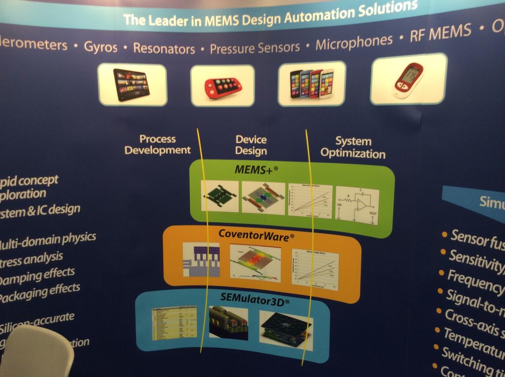
DAC has an interesting mix of vendors each year, and some of them are outside of the expected digital, analog or IP space. Last Tuesday at DAC I visited a company called Coventor that has three product lines:
- MEMS+ – MEMS design and analysis tools
- CoventorWare – Modeling and simulation for MEMS devices
- SEMulator 3D– a 3D semiconductor and MEMS process modeling tool
I interviewed Thomas Flynn of Coventor, he has been with the company four years, and previously worked at Ansoft.
Q: What is the focus of Coventor?
Our company focus is semiconductor process development, MEMS and EDA.
Q: Who are your customers?
We have a diverse set of customers: IDM, Fabless, Foundries (Both semi and MEMS).
Q: How is Coventor funded?
The company is privately held, with venture capital from: Intel Capital and Needham. We are also profitable.
Q: What are the industry challenges for MEMS design?
There are some common challenges between MEMS and semi process development. The development cycles can be long, even taking years to reach the market.
Q: How do Coventor tools help in the design of MEMS?
Coventor tools simulate the physics of a MEM.
A next generation MEMS process can take 3 years to develop, costing billions, so how do you automate some of that?
SEMulator 3D helps in process integration, technology development, because it’s a virtual fab tool. Inputs are a GDS II layout, then you add the step-by-step process description, finally the output is a 3D silicon-accurate Model.
Q: Are there alternatives to using Coventor tools?
Yes, the alternatives are to follow the traditional build and test cycle, or write your own internal tools.
Q: How does SEMulator 3D help me?
With the SEMulator 3D tool both the design and process can be co-optimized. There’s a virtual metrology ability to see contacts and vias, etc. You can review the 3D database and find failures virtually before fabrication.
Q: Where are you talking about Coventor at DAC?
We have a panel discussion tomorrow – Booth 313 at 10:15AM, on IoT and Sensors.
Q: When would a fab use a process simulation?
During process integration and development you could run lots of real silicon and then wait 3 months to measure results, where the cycle of learning can be $50M per lot. In contrast you can instead do a virtual cycle of learning in about a week.
The Coventor approach is to use a Voxel-based algorithm (3D squares of the same size). We recently resented a validation paper at SISPAD conference for 22nm technology, showing the impact on yield by optimizing with SEMULATOR (IBM). They did 2-3000 virtual simulations in just a few weeks to tune for yield, which then allowed them to change both the design and the process.
In a 3 year cycle of process learning you can start to save up front in the first half by removing complete cycles, uncover systematic failures, and understand defect evolution.
Q: How are MEMS analyzed and simulated?
We use Finite Element Analysis – extract a model of a 3D structure, extract a SPICE model. A closed loop simulation in MEMS is required. The traditional way to design MEMS is very complex with thermal, mechanical, fluid and electrostatics analysis. Much of MEMS is also a build and test approach. It’s a serial design process, and the IC designers have to wait months to get a SPICE model.
We do MEMS layout and a SPICE model at the same time for simulation. We start out with a library of commonly used shapes, pre-solved, in high order models.You also need to have the electro-model coupling. A gyro MEMS device can be built and exported out to Matlab model and Simulink simulation, or to Virtuoso in Verilog-A (a linearized model for fast speed). This model could then be run in any Verilog-A simulator. We also can simulate full non-linear models, where you decide how much accuracy versus simulation speed is need. You can physically watch the movement of the MEMS devices during simulation.
Q: How would a customer do an evaluation of your tools?
Evaluations – can be paid, where specialists go on site and join the team to get the best results in the quickest amount of time.
Q: Are there any MEMS standards?
Enabling MEMS PDKs – this is something new for the MEMS industry because of little standarization, although this is now changing. Will my MEMS device really work? Use MEMS+ and see if this device will work across process variations, will it yield well, looking at both the components and the components in a system. A MEMS fab could use a MEMS library to ensure quicker success.
Structural verification of a MEMS is another emerging area, did I violate any MEMS rules? Pinpoint where I violated a MEMS rule.
lang: en_US
Share this post via:


Comments
There are no comments yet.
You must register or log in to view/post comments.