

The power integrity (PI) of a system is an extremely important aspect to be looked at all levels – chip, package and PCB for overall reliability of the system. At the PCB level, a DC analysis, usually based on IR drop, must ensure that adequate DC voltage, satisfying all constraints of current density and temperature, is delivered to all active devices mounted on the PCB. Similarly an AC analysis must ensure that proper AC current, satisfying all constraints of transient noise voltage levels within the PDN (power delivery network), is delivered to all devices for their proper switching. It’s not as simple as it looks; temperature dependence of metal conductivity brings non-linearity in IR drop analysis. In case of AC analysis, the aspects of frequency dependence, inductance, plane capacitance, decaps (decoupling capacitances), plane-to-plane coupling and resonances, and the like make it much more complex. There are commercial tools available for these analyses which employ multi-physics principles and intensive algorithms for PI analysis at DC as well as AC level. Cadencehas tools such as Sigrity PowerDC, PowerSI and Sigrity Speed2000 (for time-domain analysis). Sigrity OptimizePI is a tool that can be used to reduce the PDN noise by applying suitable decaps.
However, the reason of my pondering over this topic today is for an interesting powerful capability that these tools together offer for front-to-back PCB PI analysis which channelizes the efforts of design engineers, layout engineers and PI analysis expert in the most efficient manner to produce the best results at the most optimized use of resources.
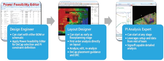
By using Cadence’s Allegro Sigrity PI (which uses constraint-based PI approach for PCB and IC package designs) design engineers at the front-end and layout engineers at the back-end can contribute earlier and more effectively to PCB PI. The DC and AC PI analysis capabilities are in-built for PI optimization and signoff. The constraint-based design methods provide a uniform interface for design-intent information exchange between front-end and back-end.
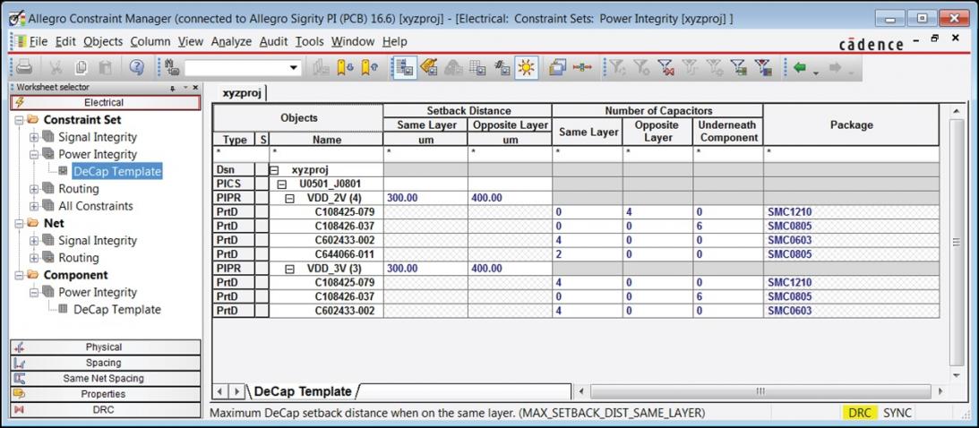
The Allegro Constraint Manager is used to manage PI constraint sets (PI Csets) for all components. PI Csets contain information for each power rail, including decap component names and quantities, package type, and physical placement guidance. The designers can use Power Feasibility Editor to create PI Csets for components to define their PI design intent. The layout designer gets the information about placement guidance and power rail association for decaps for a reliable placement. The Power Feasibility Editor also provides access to approximate and detailed pre-layout analysis for selection and placement of decaps. In the absence of impedance data from device vendors, high-level specifications can be made to generate target impedance profiles. Sigrity OptimizePI can be used for automatic generation of PI Csets.
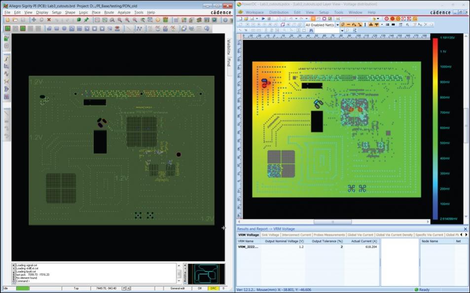
[Split-screen view of layout (left) and IR drop analysis results (right)]
For the layout designers to dynamically update metal shapes and vias to address IR drop and current constraint issues, Allegro Sigrity PIprovides access within the layout environment to the setup and result display for DC IR drop and current constraint analyses through split-screen view. This allows layout designers to analyze the situation and identify PI issues much before the PI analysis expert gets involved.
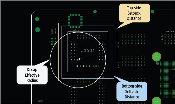
Decap Placement Guidance is a very important feature which can strongly influence the success of AC PI and the routing of wires in general. A decap placed very close to a device can be beneficial for PI, but can restrict routing channels due to decap mounting vias. Similarly, a decap too far from a device can be ineffective in providing switching current to the device and can negatively affect PI. The Sigrity PIprovides a decap placement mode through which a component and a power rail can be selected and then an excellent placement guidance follows with cursor movement, point and click. In the example picture, device to decap distances for top and bottom layers, and decap effective radius (within which the decap will be maximally effective) are shown. The decap value is dynamically computed as the cursor moves.
The overall process makes the design intent and analysis setup information ready for detailed PI analysis by the PI analysis expert. The information about fine adjustments between the front-end and the back-end flows seamlessly for design engineers, layout engineers and PI analysis expert to make necessary updates in their parts and keep them in sync.
Although there are good tools available to serve the purpose of PCB PI analysis, this approach of constraint-based front-to-back comprehensive flow realised by Allegro Sigrity set of tools can be quite effective in terms of resource utilization and quality of results. A more detailed description about the flow and tools can be found in a whitepaperwritten by Brad Brim at Cadence.
More Articles by Pawan Fangaria…..
lang: en_US


Comments
There are no comments yet.
You must register or log in to view/post comments.