

At the onset of SoCs with multiple functionalities being packed together at the helm of technologies to improve upon performance and area; power, which was earlier neglected, has become critical and needs special attention in designing SoCs. And there comes reliability considerations as well due to multiple electrical and physical effects coming into existence at lower nodes and high density of SoCs. Both, power and reliability of chips need specific focus to analyze and fix issues at the earliest in the design phase.
I was all ears to a webinar presented by N. Kannan of Freescale Semiconductorwho talked in great detail about how they are tackling the challenges of power and reliability in their advanced automotive and networking SoCs; and also on how they are leveraging Apachetools like RedHawk[SUP]TM[/SUP], Totem[SUP]TM[/SUP], CPM[SUP]TM[/SUP], PathFinder[SUP]TM[/SUP], PowerArtist[SUP]TM[/SUP], Sentinel[SUP]TM[/SUP]and others for these purposes. It extremely impressed me knowing about various capabilities of these tools and prudence being exercised at Freescale in designing SoCs. It’s my pleasure to introduce below just a glimpse of those.
Automotive SoCs typically have on-chip Flash, Power Management Unit (PMU) and Analog IPs with multi-power domain and require PCB-Package-Die sign-off for electromagnetic compliance. Networking SoCs, on the other hand, have very large design sizes with multiple cores running at high frequencies, thereby requiring high peak and average power consumption. Package-Die sign-off for power integrity, signal integrity, simultaneous switching output and thermal conduction is a must for these SoCs.
RedHawk[SUP]TM[/SUP]is used for electrical as well as physical modelling. In case of standard cells, modelling of current and capacitance can be done by using Apache Power Library (APL) format. Current de-rating due to voltage drop is captured in the model. In case of Multi-Bit Flops, RedHawk[SUP]TM[/SUP]simplifies the modelling by approximation to the tune of just n characterizations for an n-bit flop. In case of a memory, RedHawk[SUP]TM[/SUP] is able to recognize bit-cell array regions inside the memory and provide more accurate distribution of currents and capacitances.
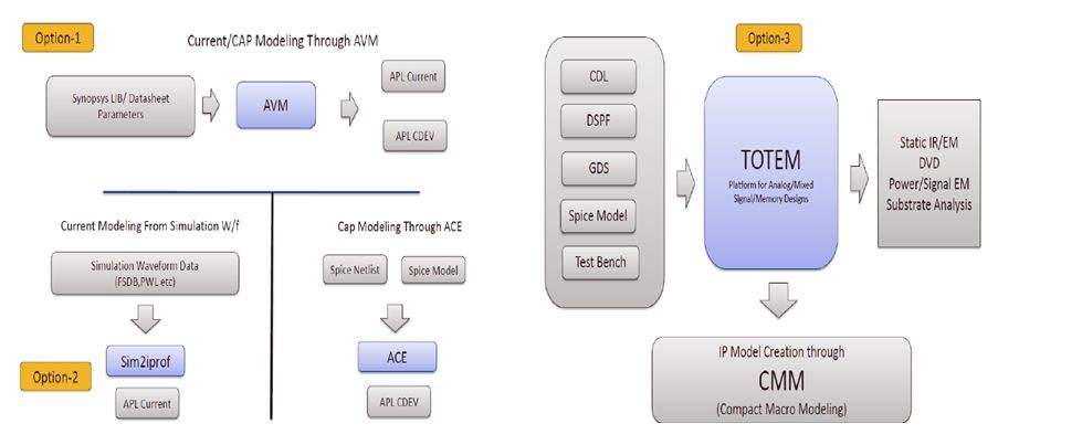
[Electrical Modelling Options]
Depending on size and nature of the design any or all of these three options can be used for electrical modelling. Option-1 is very simplistic model based on approximation; option-2 is most commonly used where full simulation data is used and option-3 is most expensive on run time where transistor level modelling is done using Totem[SUP]TM[/SUP]. This provides full simulation based analysis and is used in cases such as Flash where uniform current distribution is required.
RedHawk[SUP]TM[/SUP] provides extensive checks for connectivity and reliability such as weak spots in the grid, resistance bottlenecks (through short path tracing), missing vias, EM violations, IR drop bottlenecks, current hot-spots and so on; and provides what-if scenario analysis on IR and EM by using region based power assignment.
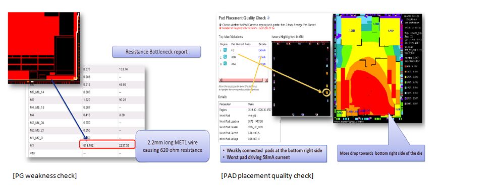
As an example, a long wire high resistance is pointed out during PG weakness check and a PAD consuming very high current during PAD placement quality check. PAD placement needs to be optimized with respect to average current ratio.
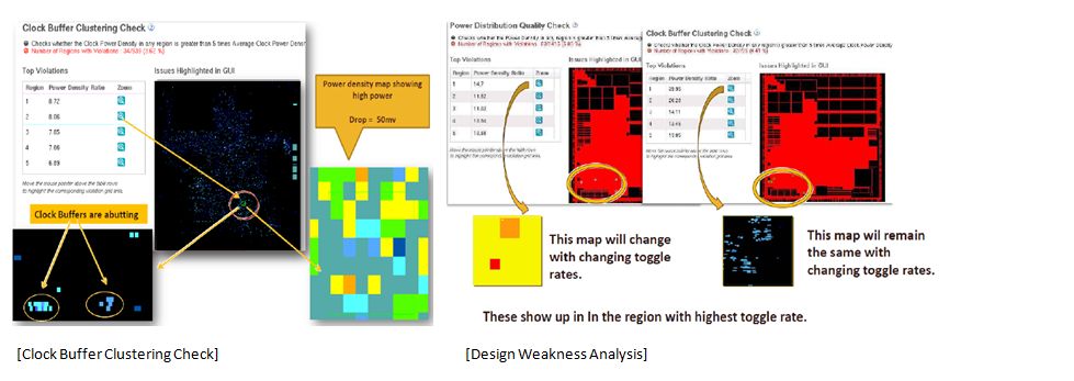
Similarly, clock buffers may be clustered in a particular region, leading to high switching and power density there, which needs to be fixed.
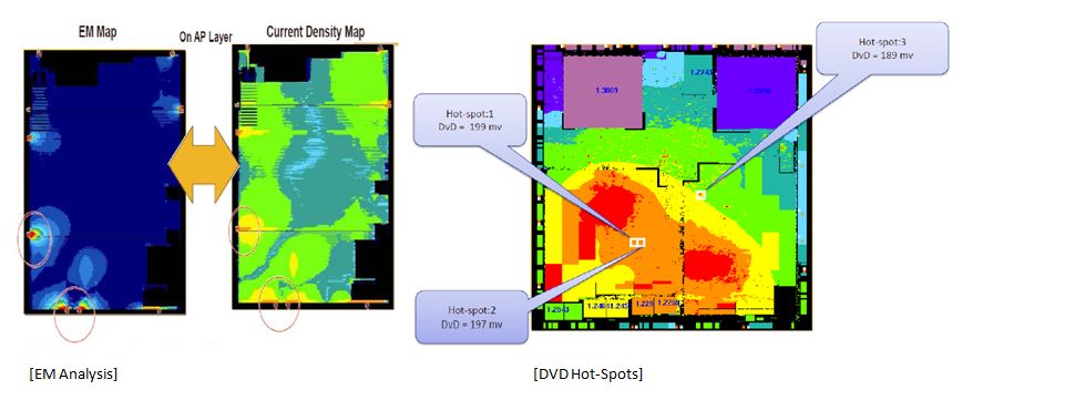
EM violations in regions of high current sourcing such as PAD locations and hot-spots due to excessive dynamic IR drop in regions with high activity logic clustering need fixes.
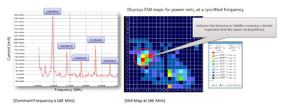
CPM[SUP]TM[/SUP](Chip Power Model) is used to do compact abstraction of full chip Power Distribution Network (PDN). Chip, package or board level simulation can be done. Frequency spectrum of chip current demand can be obtained. Time domain analysis can be done for the chip-package. High frequency noise associated with high peak current and corresponding layout regions can be identified and corrected for EM compliance.
Kannan also talks about reliability sign-off done by using Totem[SUP]TM[/SUP]on standard cells. They are also working on using PathFinder[SUP]TM[/SUP]for ESD and current density checks and PowerArtist[SUP]TM[/SUP]for RTL power estimation and reduction. They are working with Sentinel[SUP]TM[/SUP] for Chip Power density and Thermal Map analysis.
The actual delivery of the webinar is very exhaustive, containing details about various problems and the ways to fix them. This presentation was also done in DAC2013. Thanks to Apache and Freescale for making it freely available for our larger community. The webinar, titled “Power, Noise and Reliability Consideration for Advanced Automotive and Networking ICs” can be found here.


Comments
0 Replies to “Power and Reliability Sign-off – A must, but how?”
You must register or log in to view/post comments.