

Ground. It’s that little downward-pointing triangle that somehow works miracles on every schematic. It looks very simple until one has to tackle modern power distribution network (PDN) design on a board with high speed and high power draw components, and you soon discover ground is a complicated fairy tale with a lot of influences.
No amount of signal integrity analysis will save a design if the power integrity is lacking. We’ve been looking around at various tools for power and signal integrity, and I wanted a closer look at the Mentor Graphics offering. HyperLynx 9.0 is making its debut with new features for DDR memory analysis and more, but the baseline of features for power integrity analysis is intact from the prior version.
I grabbed an oldie-but-goodie Mentor webinar on “Design for Signal & Power Integrity with HyperLynx 8.0”, featuring independent consultant Dr. Eric Bogatin and Chuck Ferry of Mentor talking through the subtleties of PDN analysis. Eric proposed three basic goals for any design: providing stable voltages to the chip pads across the spectrum from DC to more than the bandwidth of signals; providing a low impedance return path (the correct name for “ground”) for signals; and mitigating EMI.
He then injected the first dose of reality: what does 100A look like, anyway? We think of high amperages involved in something like the circuit breaker panel on the side of our building, or in gigantic chunks of copper. On boards with multiple processors, power supply current on primary voltages can add up quickly, including spikes from simultaneous switching of signals. He sets a goal of 1mOhm impedance, from DC to GHz ranges, for a PDN.
In a simple fairy tale, there are 3 “habits” to minimize PDN impedance. The first is to place power and ground planes on adjacent layers separated by a thin dielectric, close to the surface if possible. The second is to use short surface traces for decoupling capacitors. The third is to choose the number and values of decoupling caps to fine-tune the impedance profile where needed.
In the full-length book of short stories, the darker characters in the PDN show up. There are lots of voltage rails on a board, each with characteristics of loading and decoupling. There are not enough planes as a result, and even good planes are non-optimally shaped or look more like Swiss cheese underneath difficult components (often the highest current draws). Space is always at a premium, so locating the decoupling caps may be a struggle.
Coping and hoping used to be the strategy: do what worked on prior designs, go to the “guru” and ask for his layout advice, or dump a lot of margin in with more layers to accommodate planes and more decoupling. In a better strategy, design rules and virtual prototyping enter the story to help create a “correct by design” environment with the minimum margin needed for performance goals, which helps minimize cost.
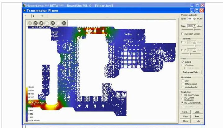
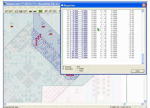
Chuck then showed some of the capability of HyperLynx in analyzing power integrity. The first is pictured above: being able to look at current density and IR drop across the layout, with the red and yellow areas where things are happen. At a more detailed level, HyperLynx can drill down and look at simulated current at each via, quickly revealing possible problem areas that may need rerouting or additional traces (usually not enough ground vias) to deliver current.
This type of post-layout visualization of power integrity can head off problems before they ruin a design. There is nothing more evil than trying to debug an elusive voltage drop on a critical area of a physical prototype, burning braincells on power instead of signaling performance. Mentor is even offering a cloud-based version of HyperLynx PI for designers to try it out.
In your experience, is the empirical wisdom of the guru still enough to succeed in power distribution on boards, or is something more analytical needed to navigate the fairy tale? Have you tried HyperLynx PI and have some thoughts? Where are you still running into problems where new tools might help? Thoughts welcome.


Comments
There are no comments yet.
You must register or log in to view/post comments.