

Preventing electrical circuit failure is a growing concern for IC designers today. Certain types of failures such as electrostatic discharge (ESD) events, have well established best practices and design rules that circuit designers should be following. Other issues have emerged more recently, such as how to check circuits for correct supply connections when there are different voltage regions on a chip in addition to other low power and electrical overstress (EOS) issues. While these topics are not unique to a specific technology node, for analog and mixed signal designs they become increasingly critical as gate oxides are get thinner for the most advanced nodes and circuit designers continue to put more and more voltage domains into their designs.
In addition to ESD protection circuit errors, some of the emerging problems that designers may face at advanced nodes include:
- Possible re-spins due to layout errors
- Thin-oxide/low-power transistor gate driven by the wrong (too high) voltage supply causing transistor failures across the chip
- This might also cause degradation over a period of time, leading to reliability issues and product recalls
- Chip reliability and performance degradation
- Un-isolated ground/sink voltage levels between cells or circuits
- High-voltage transistors operating in non-saturation because of insufficient/low-voltage supply
TSMC and MGC have worked together to define and develop rule decks for Calibre® PERC™ that enable automatic advanced circuit verification that addresses many of these issues. For example, in TSMC Reference Flow 11 and 12, and in AMS Reference Flow 1 and 2, as well as in standard TSMC PDK offerings, MGC and TSMC have collaborated to provide checks for ESD, latch-up and multi-power domain verification at the 28nm and 40nm nodes. The companies estimate that by using a robust and automated solution like Calibre PERC, users can achieve over 90% coverage of advanced electrical rules with no false errors and runtimes measured in minutes. This is a significant improvement over marker layers, which may achieve around 30% coverage and often result in false positives, and it is far better than visual inspection, which typically achieves only about 10% coverage and is extremely labor intensive.
Calibre PERC introduces a different level of circuit verification capability because it can utilize both netlist and layout (GDS) information simultaneously to perform checks. In addition, it can employ topological constraints to verify that the correct structures are in place wherever circuit design rules require them. Here is a representative list of the checks that Calibre PERC can be used to perform:
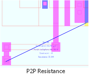
- Point to point resistance
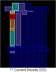
- Current density
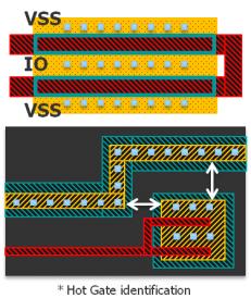
- Hot gate/diffusion identification
- Layer extension/coverage
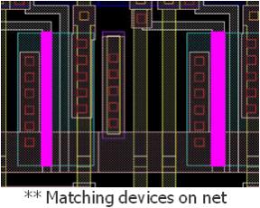
- Device matching
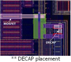
- DECAP placement
- Forward biased PN junctions
- Low power checking
- Thin-oxide gate considerations, e.g., maximum allowable voltage
- Voltage propagation checks, e.g., device breakdown and reverse current issues
- Detect floating gates
- Verify correct level shifter insertions and correct data retention cell locations
- Checks against design intent annotated in net lists
- Matched pairs
- Balanced nets/devices
- Signal nets that should not cross
- MOS device guard rings
Customers are constantly finding new ways to employ Calibre PERC to automate new types of circuit checks. Leave a reply or contact Matthew Hogan if you would like to explore how Calibre PERC might be used to improve the efficiency and robustness of new or existing checks.
by Steven Chen, TSMC and Matthew Hogan, Mentor Graphics
Acknowledgements
The authors would like to recognize members of the TSMC R&D team Yi-Kan Cheng, and his teams, Steven Chen, MJ Huang, Achilles Hsiao, and Christy Lin, as well as the entire Calibre PERC development and QA team for their support and dedication in making these outstanding capabilities possible.
This article is based on a joint presentation by TSMC and Mentor Graphics at the TSMC Open Innovation Platform Ecosystem Forum. The entire presentation is available on line on theTSMC web site (click here).
var _gaq = _gaq || [];
_gaq.push([‘_setAccount’, ‘UA-26895602-2’]);
_gaq.push([‘_trackPageview’]);
(function() {
var ga = document.createElement(‘script’); ga.type = ‘text/javascript’; ga.async = true;
ga.src = (‘https:’ == document.location.protocol ? ‘https://ssl’ : ‘http://www’) + ‘.google-analytics.com/ga.js’;
var s = document.getElementsByTagName(‘script’)[0]; s.parentNode.insertBefore(ga, s);
})();


Comments
There are no comments yet.
You must register or log in to view/post comments.